3D45 Mechanical & Electrical
- Leveling Arm Replacement
- Camera Replacement
- Build Platform Clip Replacement
Leveling Arm Replacement
This video will walk you through a step-by-step instruction on how to properly replace the leveling arm
on your Dremel 3D45 Printer.
You can also download the PDF instructions here.
Instructions
Use proper anti-static precautions when performing this replacement. Discharge static electricity before beginning. Work on a static-free surface.
This document will outline the steps necessary to replace a defective or damaged leveling assembly. This includes the leveling switch, servo motor, and mounting bracket.
Tools required
• Scissors
• 2mm Hex bit or Hex wrench (Allen key)
• T10 Torx (star) or screwdriver bit
Step 1: Bring Printer to Safe State
Allow the build plate and nozzle to cool down before handling. Turn off and unplug printer then wait for 15 min to allow the nozzle and build platform to cool down to a safe temperature (below 60°C).
Step 2: Remove Top Cover on the Extruder
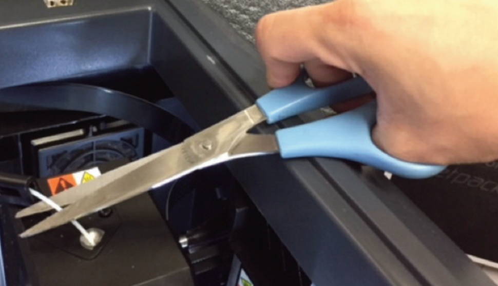
a) Cut the filament just before the intake on the top of the extruder.
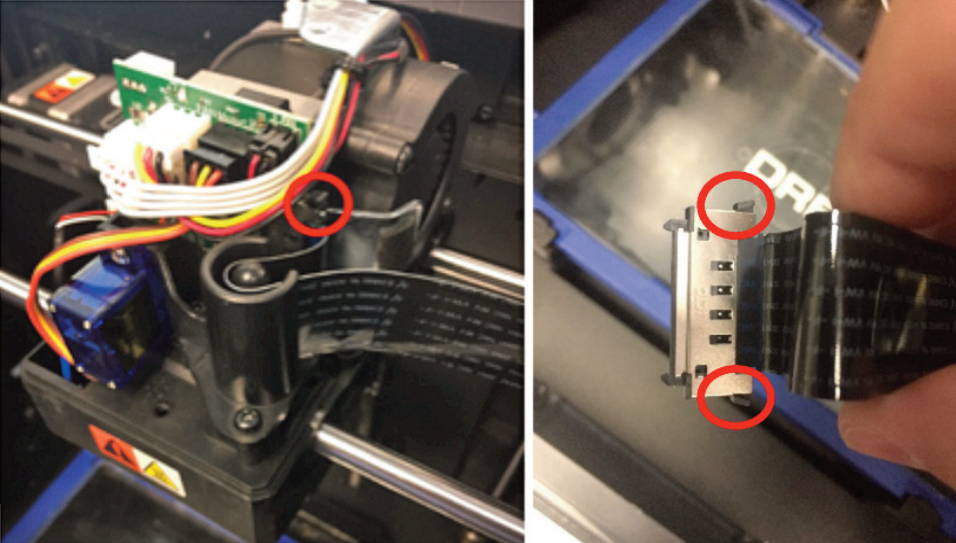
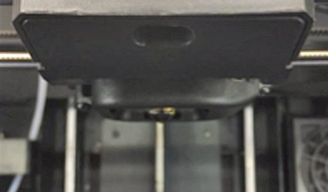
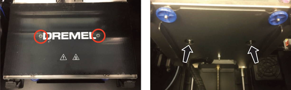
Figure 3a (Left) Figure 3b (Right)
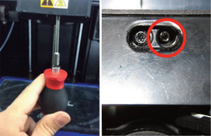
b) Remove screw located on the right side hole using the T10 Torx screwdriver. Figure 3a above shows the location of the screw, and Figure 3b shows a bottom view of the area where the screw is located.
Circled in red, is the screw that needs to be removed. Remove screw located on the right side on the bottom of extruder
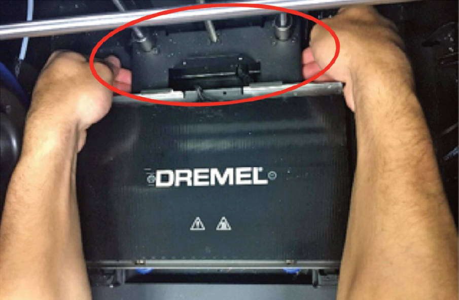
c)Unscrew the two screws on the top of the filament guide bracket using the 2.5mm Hex wrench.
d)Remove the top cover.
e)Carefully unplug filament run out switch from the extruder circuit board, ensuring to pull from the plastic plug and not the wires; pulling the wires can damage the connection to the extruder.
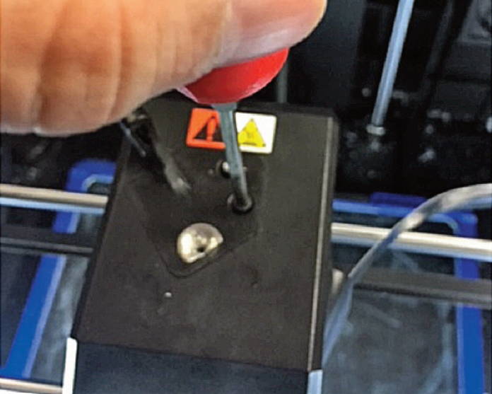
Step 3: Remove Shielded Circuit Cable

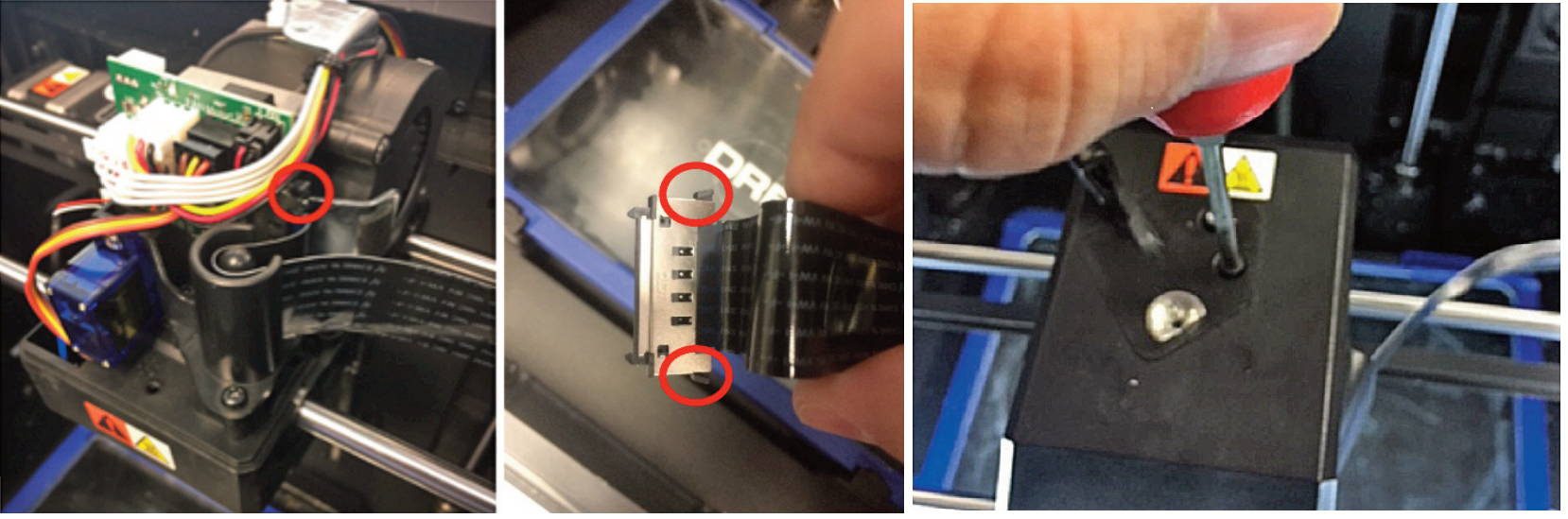
a) Using the 2 black push pins (encircled red) of the shielded circuit ribbon cable, push down to release it from the circuit board..
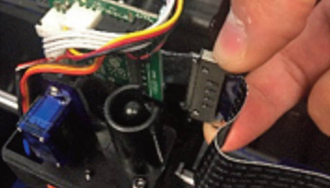
b) Remove the connector from the circuit board and pull up on the cable. Always use great care when handling a shielded circuit cable.
c) Set aside the cable within the machine, making sure there are no sharp kinks or turns produced.
Step 4: Remove the Leveling Servo Assembly
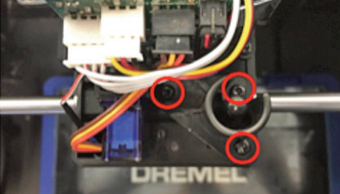
a) Remove the three screws holding the servo motor bracket in place with a T10 Torx (star) bit.
b) Get a visual understanding of how the levelling arm is located and oriented in the assembly, rotate the leveling arm to vertical position (see picture above), and then pull the servo motor assembly vertically upwards away from the extruder.
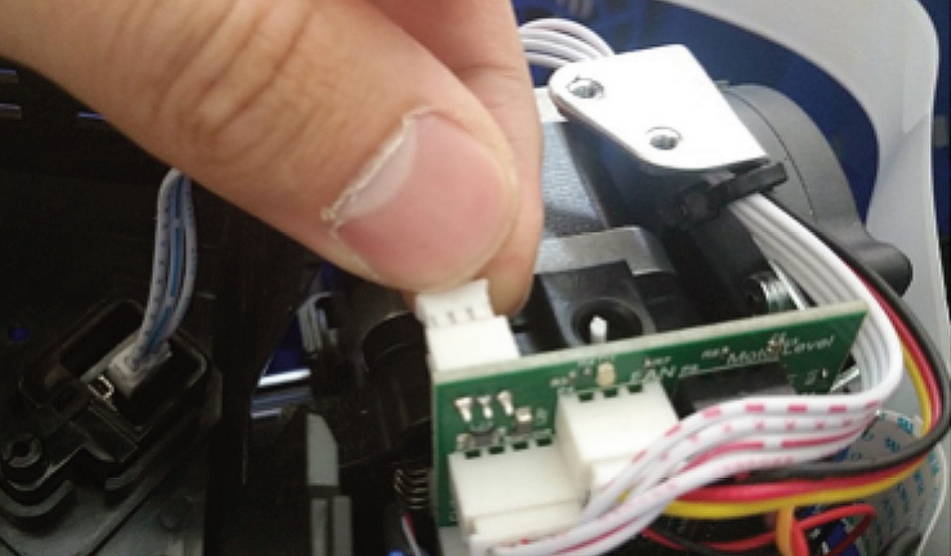
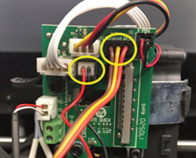
Step 5: Disconnect the Extruder Circuit Board

a) Disconnect the leveling switch (black and red wires) and servo motor (red, brown, and yellow) from the extruder circuit board. When removing these, always remove by the plastic connectors. Never pull by the wires, this can damage or break the connectors.
Step 6: Reassemble the Extruder

a) Replace the leveling servo assembly carefully by maneuvering the levelling arm through the extruder chassis.
b) Replace the three screws holding the servo motor chassis in place as shown in Step 4 (see picture above).
c) Reconnect both wire connectors to the extruder circuit board as shown in Step 5 (see picture above).

d) Loop the shielded circuit cable through the plastic guide bracket as shown in Step 3 (see picture above).
e) Press the black connector pins on the shielded ribbon cables and align with the receptacle. Gently push the ribbon cable onto the receptacle and release the black pins. An audible “click” should be heard when it is reconnected.
f) Reconnect the filament runout switch from the extruder top cover to the circuit board.
g) Replace the top cover and the three (two on top, one on bottom) screws attaching it to the extruder.
NOTE: After replacing the top cover, ensure that no wires are exposed out of the extruder body. If any wires are exposed or hanging out, the extruder top cover will need to be removed and replaced.
Step 7: Calibration
This step will outline how to calibrate the leveling arm. The replaced leveling arm does not know where it is in rotation before calibration, so the following instructions will calibrate it to the correct position.
a) Navigate to TOOLS>SETTINGS>SERVICE TOOLS>LEVELING SWITCH
b) The leveling switch tool will show up on the screen. The Up and Down orientations have + and - adjustment buttons. The adjusted angle can be seen in the gray box between the + and – buttons.
i. Press “test” once to move the levelling arm down.
ii. Ensure the leveling arm is vertical (straight up/down) as shown in picture above.
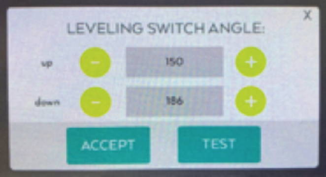
If not, press + to increase angle or – to decrease angle in front of “down” as shown in picture above.
iii. Press “test” twice to check the orientation after adjustment in vertical position. If not satisfied with the orientation of the arm, repeat step i. and ii. until desired orientation is achieved in vertical position.
iv. Press “test” once to move the arm in the stow position.
v. Ensure the leveling arm is NOT exposed like it is shown in picture above.
vi.If yes, press - to decrease angle in front of “up” in "Leveling switch angle" screen (previous image).
vii. If the arm makes a hitting sound or rebounds back while stowing, then it is stowing too high. In that case, press + to increase angle of stowing in front of “up”. The arm should be stowed as shown in the picture above, such that it doesn’t expose or rebound.
viii. Once the angles are adjusted for both vertical and stowing positions, press “Accept”.
Dremel 3D45 Camera Replacement
This page will walk you through how to properly remove your Dremel 3D45 Camera for replacement. Watch the video for an overview or download the PDF instructions here.
Instructions
This document will outline the steps necessary to replace a damaged build platform clip.
Tools Required
• T10 Torx (star) screwdriver
Step 1: Bring Printer to Safe State
Allow the build plate and nozzle to cool down before handling. Turn off and unplug printer then wait for 15 min to allow the nozzle and build platform to cool down to a safe temperature (below 60°C).
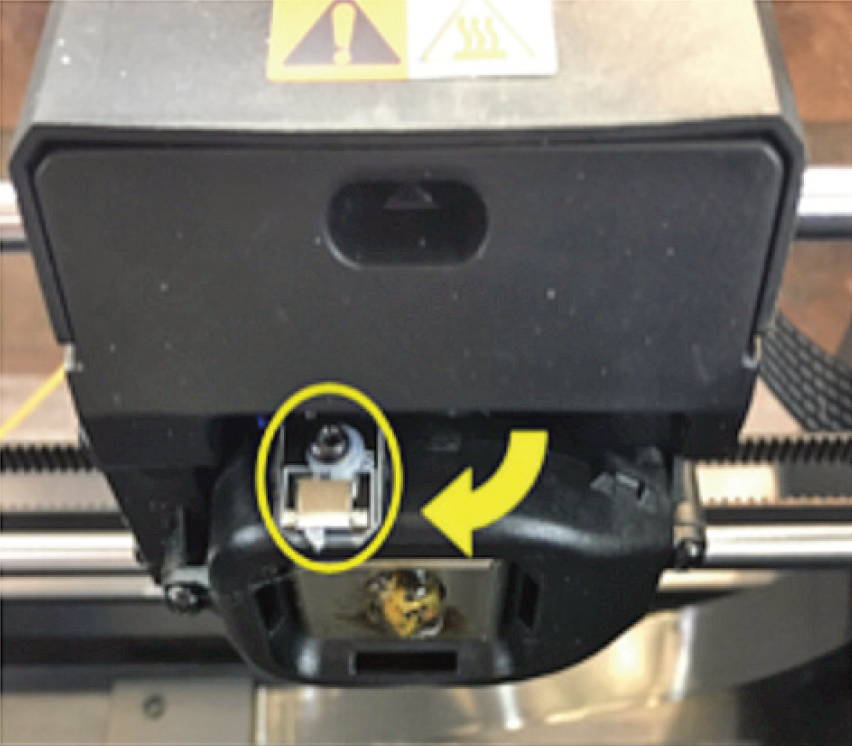
Step 2: Remove the Camera from Printer
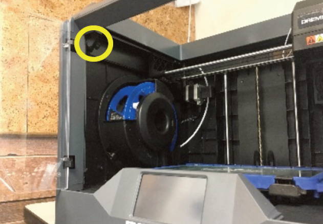
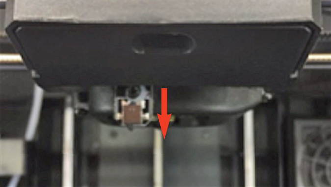
a) Locate the camera in the printer.
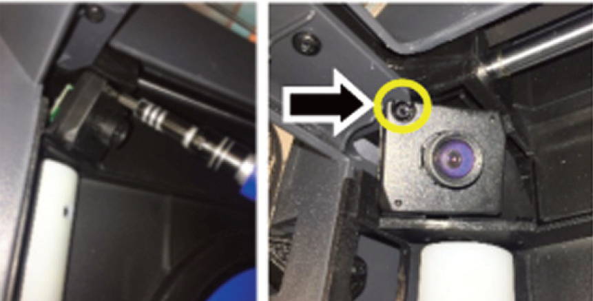
b) Remove the screw located on the top left side of the camera using the T10 Torx screwdriver.
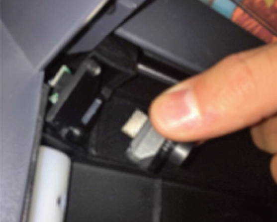
c) Pull the camera outwards (see red arrow below) to unplug the USB connection
Step 3: Reassemble the Camera

a) Plug the camera back into the printer

b) Replace the screw using the T10 Torx screwdriver, securing the camera to the printer
Build Platform Clip Replacement
This page will walk you through 7 steps to properly replace your platform clips for proper attachment of
the build plate.
You can also download the PDF instructions here.
Instructions
This document will outline the steps necessary to replace a damaged build platform clip.
Tools Required
• Socket wrench
• 7/32 deep socket
• 2mm Hex bit or Hex wrench (Allen key)
• T10 Torx (star) or screwdriver bit
Step 1: Bring Printer to Safe State
Allow the build plate and nozzle to cool down before handling. Turn off and unplug printer then wait for 20 min to allow the nozzle and build platform to cool down to a safe temperature (below 60°C).
Step 2: Raise build platform
a) Remove the glass build plate from the printer.
b) Gently lift the build platform manually, as high as it will go.
Apply the force on the metal bracket on the back of the
platform (highlighted in red).
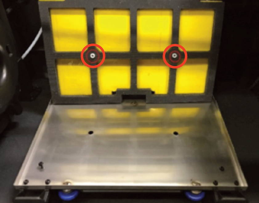
Step 3: Remove top component of the platform
a) Remove the two screws (encircled in red) using the 2mm Allen Key and socket wrench. Place the socket wrench on the
nut shown in the right picture, then use the 2mm Allen Key to loosen the screws while holding the nut with the socket wrench. There is a small washer by the nut on the bottom side, be sure not to lose it when removing the screw.
Step 4: Remove damaged build plate clips
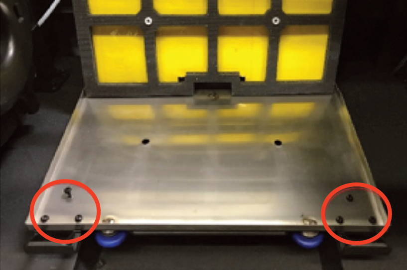
a) Lower the bed and tilt the bed components up to reveal the clip screws. Ensure the white spacers don’t fall from foam pad.
b) Remove the screws (encircled in red below) using the T10 Torx screwdriver.
Step 5: Install new build plate clips
a) Install new build plate. Refer to Step 4.
Step 6: Install top components of build platform
a) Lay components back down. Ensure that the spacers are still inserted into the foam pad (encircled in red above).
b) Raise the platform up and reinstall the 2mm Allen screws, with the small washers and nylock nuts. Refer to step 3.
Step 7: Insert glass build plate
a) Insert the build plate and ensure it is secure.