This page details the process of preparing a file to print using the Dremel Digilab 3D Slicer. This software will allow you to quickly and easily slice your file to obtain a high quality print using your Dremel 3D printer. The software is pre-loaded on the USB stick included with your printer, or click here (Windows / MAC) to download.
Dremel DigiLab Desktop Slicer Software
Based on Cura's open-source slicing software, Dremel DigiLab 3D Slicer will allow you to securely slice your CAD files without the need for internet connection. Since it's based on Cura, you can use the Dremel DigiLab 3D Slicer to slice files for not only your Dremel 3D printers, but also for your other Cura-integrated 3D printers.
For optimal performance of the Dremel DigiLab 3D Slicer, please ensure that your operating system is regularly updated to the most current version. Prior versions will not be optimized for compatibility; however, all new versions will be supported.
Note: 3D20 users must have firmware version v1.5-2018611 or later.
- Desktop Slicer Basics
- Desktop Slicer Advanced
- Simplify3D
Dremel DigiLab 3D Slicer Basics
This video will show you all of the basic steps involved in slicing an STL or OBJ 3D file into a printable file format.
 Step 1: Familiarize Yourself with the Workspace
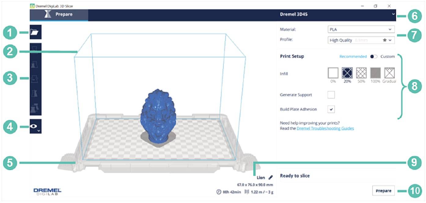
The figure above shows the interface of the Digilab Slicer with all features labeled. The features are described below:
- Open File: Import the file to be printed.
- Build Volume: The thin blue line represents the edge of the build volume, which is 10" x 6" x 6.7" (255 mm x 155 mm x 170 mm).
- File Preparation: Move, scale, rotate, and mirror the file in the file preparation tab.
- View Mode: Visualize the file as a solid, x-ray, or by layers based on the setup being used.
- Build Platform: Represents the location to where the models adhere when printing.
- Printer Selection: The software is compatible with the Dremel 3D45, 3D40, and 3D20. Ensure the correct printer is selected.
- Material and Quality: Select the material supported by your printer and the profile (quality) of the print.
- Print Setup: Adjust infill, support, and build plate adhesion settings.
- Print Estimates: Estimate print time. material required and cost after preparing the file.
- Prepare: Prepare the file to be printed based on the print setup being used.
Step 2: Select the Printer
Upon printer selection, standard settings will automatically load for that printer.

Step 3: Select the Material and the Profile
Select the material supported by your printer. Dremel 3D45 supports PLA, ECO-ABS, Nylon, and PETG. Dremel 3D40, 3D40-Flex, and 3D20 supports PLA only.
Select the print profile (quality) for your print. The quality is determined by the layer height of the print. A smaller layer height will create a more detailed part, with a longer print time. A taller layer height will print faster, but with less details depending on the part being printed. As shown in the pictures below, as you go towards a lower quality, the print layers are more visible and details may go missing. Compare the details in each quality by looking at the details of the print in a common location across the different quality levels


Step 4: Import the File
Import the file using the Open File button. Dremel Digilab Slicer supports common *.stl, and *.obj file types. The software also supports *.3mf, *.bmp, *.g, *.gcode, *.gif, *.jpeg, *.jpg, *.png, and *.x3d files.
Note: If your file is not visible after importing, zoom in to the center of the build platform and check if the file is there. It may occur that the part has been imported in different units (millimeters instead of inches), therefore importing a very small file with the wrong dimensions. In this case, hold Control + A to select all the files on the build platform, and scale the part up by 2540% to convert the dimensions from millimeters to inches. Ensure the dimensions are correct after scaling the part up.
Step 5: File Preparation
The following basic transformations can be performed to prepare the file:
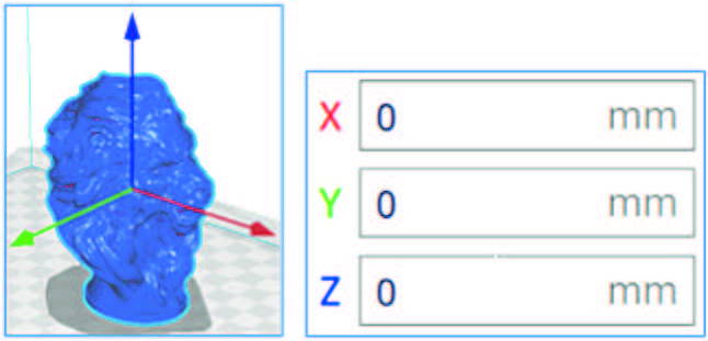
Move: Move the part along the build volume by clicking the arrows on the part (shown in the left figure below) and dragging it or inputting the distance of the translation (shown in the right figure). Ensure the part is inside the build volume and in contact with build platform.
Rotate: Rotate the file by holding and dragging on the colored lines around the file (See figure below). The angle will be changed by 15 degrees increment. Ensure that the part is in contact with the build surface.

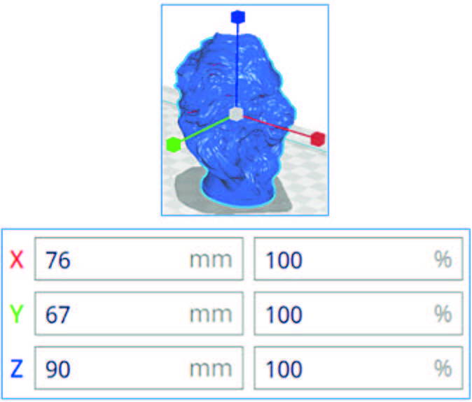
Scale: Scale the part by clicking on the file and dragging the scaling arrows (shown in the left figure), or by inputting the desired dimensions or scaling percentage (shown in the right figure). Check the uniform scaling option in order to make the scaling consistent in X, Y, and Z axes. Ensure the part is inside the build volume.
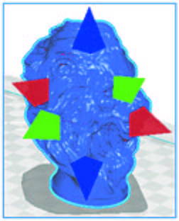
Mirror: Mirror the part across a certain plane by clicking on the arrows around the file.
Note: If the part appears not as a single solid color, it means that the part is not inside the build volume, and therefore will not be printed. Adjust the file size and placement until the solid color is achieved.
Step 6: Adjust print setup
Infill, support, and build plate adhesion settings can be adjusted under Print Setup.

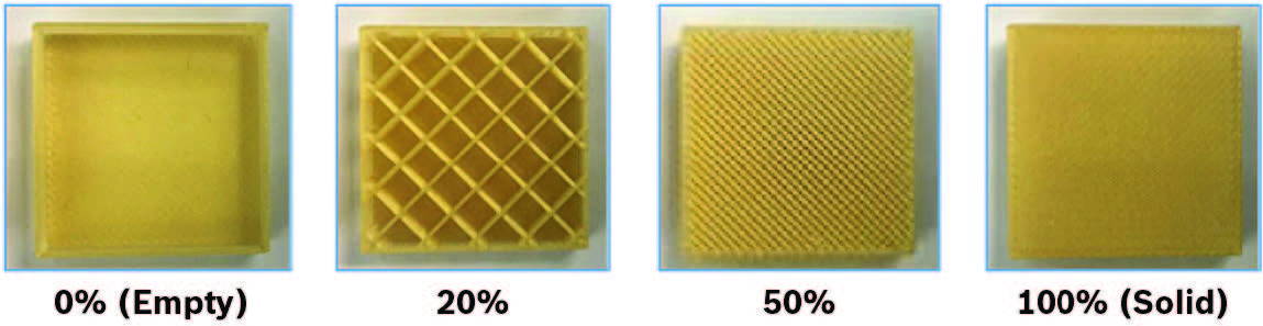
Infill: The infill is the internal support material in the part. The infill percentage can be adjusted from 0% (empty) to 100% (solid). Higher infill results in a stronger and heavier part, with a longer print time. Smaller infill results in a lighter part with a faster print time. Gradual infill will gradually increase the amount of infill towards the top of the model.
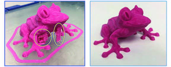
Support: Support structures (encircle in yellow below) will be printed where there are overhangs on the part. Without these structures, the model would not be able to be printed. Those supports can be removed after the part has been printed (see picture on the right).
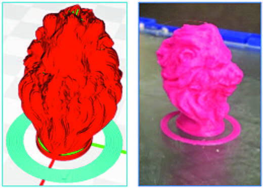
Build Plate Adhesion: This setting enables printing a skirt under recommended settings (see picture below), which will add a flat area around or under the object that can be easily removed after printing.
For advanced users, select Custom under print setup. That enables a wider range of print settings to be adjusted, creating the optimal print setup for your print.
Step 6: Prepare Button After the print setup has been adjusted, the file is ready to be sliced. Hit the prepare button and the software will create a file that can be 3D printed.
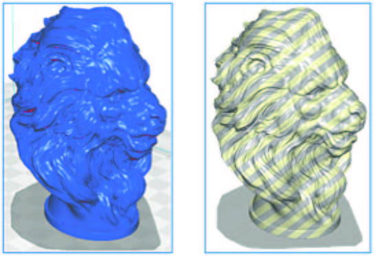
Step 7: Review the file The last step prior to saving the sliced file is to review it to ensure there are no issues. Under View Mode, there are three options to visualize the file: solid, x-ray, and layers. Solid and layers view modes are described below: Solid View Mode: Utilize the solid view mode to ensure there are no gaps or missing sections within the part. Parts with a width smaller than 0.4mm will not be printed. This mode will also assist you deciding whether the part requires support or not. Surfaces that appear red (see picture below encircled in yellow) may require support structures when printing.
Solid View Mode: Utilize the solid view mode to ensure there are no gaps or missing sections within the part. Parts with a width smaller than 0.4mm will not be printed. This mode will also assist you deciding whether the part requires support or not. Surfaces that appear red (see picture below encircled in yellow) may require support structures when printing.

Layers View Mode: This mode is crucial to ensure there are no missing layers, gaps or missing sections. Select Line Type under color scheme to identify the different line types. Hold and drag the blue dot (encircled in red below) on the vertical line to visualize how the layers are being printed.


Also, review the print estimates. The software will estimate the print time, filament necessary and part weight. You can rename the file by clicking on the pencil symbol (encircled in red bellow) next to the name.

Step 8: Save file to USB drive
Save the file to a removable drive or to the computer. The software will automatically generate a *.gcode file that can be 3D printed. The file can be sent directly to the printer using an Ethernet connection.
Dremel DigiLab 3D Slicer Advanced
In this video tutorial, you will find out how to:
- Connect your 3D printer to print over LAN
- Activate all custom settings
- Create & save a custom printing profile
- Create a custom material profile
- Fine tune your supports for the best outcome
- Enable Dark Mode
- Explore some of the 300+ Special & Experimental Modes
Dremel 3D Printers Now Compatible with Simplify3D
Improve your print quality with the most powerful 3D printing software available. Simplify3D® provides complete control over your print settings, making it easier than ever to create high-quality 3D prints. Start up quickly with pre-configured settings optimized for Dremel's 3D Printers, review a simulation of your build sequence in the Preview Mode, and begin your 3D print with confidence. Total control means amazing 3D prints!
Simplify3D is not included with your Dremel 3D Printer and must be purchased separately.